ASTM B338
ASTM B338
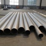
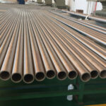
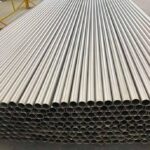
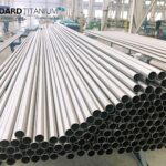
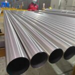
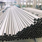
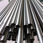
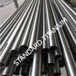
Seamless and Welded Titanium and Titanium Alloy Tubes for Condensers and Heat Exchangers
The standard ASTM B338 is the industry standard for the production of titanium tubes for use in applications including:
- Heat exchangers
- Condensers
- Evaporators.
It is the most commonly used standard worldwide when specifying titanium tubing.
The standard is used to specify titanium tubes irrespective of form (Seamless Tubing or Welded Tubing).
A previously available separate standard ASTM B337 existed for the specification of tubes outside of the applications at the focus of ASTM B338 however has now been withdrawn in favor of two separate standards (ASTM B861 and ASTM B862) which treat the separate forms (Seamless / Welded) in differing ways

Contact us today for your Titanium
We're dedicated to helping our customers succeed
All orders are quoted individually and we aim to quote all enquiries within 24 hours. Quotes will detail if product is in stock and delivery times. To help us get the right information to you, please provide:
- Product Required
- Size & Quantity
- Any Specific Standards
- Destination / Shipping Terms
Chemical Composition
The specification covers the grades of titanium and to manufacturer to a the following given set of chemical content and limits for the particular grade.
| Grade | Nitrogen, max | Carbon, max | Hydrogen,B,C max | Iron, max | Oxygen, max | Aluminum | Vanadium | Tin | Ruthenium | Palladium | Cobalt | Molybdenum | Chromium | Nickel | Niobium | Zirconium | Silicon | Residuals,D,E,F max each | Residuals,D,E,F max total | TitaniumG |
|---|---|---|---|---|---|---|---|---|---|---|---|---|---|---|---|---|---|---|---|---|
| 1 | 0.03 | 0.08 | 0.015 | 0.2 | 0.18 | 0.1 | 0.4 | Balance | ||||||||||||
| 2 | 0.03 | 0.08 | 0.015 | 0.3 | 0.25 | 0.1 | 0.4 | Balance | ||||||||||||
| 3 | 0.05 | 0.08 | 0.015 | 0.3 | 0.35 | 0.1 | 0.4 | Balance | ||||||||||||
| 7 | 0.03 | 0.08 | 0.015 | 0.3 | 0.25 | 0.12–0.25 | 0.1 | 0.4 | Balance | |||||||||||
| 9 | 0.03 | 0.08 | 0.015 | 0.25 | 0.15 | 2.5–3.5 | 2.0–3.0 | 0.1 | 0.4 | Balance | ||||||||||
| 11 | 0.03 | 0.08 | 0.015 | 0.2 | 0.18 | 0.12–0.25 | 0.1 | 0.4 | Balance | |||||||||||
| 12 | 0.03 | 0.08 | 0.015 | 0.3 | 0.25 | 0.2–0.4 | 0.6–0.9 | 0.1 | 0.4 | Balance | ||||||||||
| 13 | 0.03 | 0.08 | 0.015 | 0.2 | 0.1 | 0.04–0.06 | 0.4–0.6 | 0.1 | 0.4 | Balance | ||||||||||
| 14 | 0.03 | 0.08 | 0.015 | 0.3 | 0.15 | 0.04–0.06 | 0.4–0.6 | 0.1 | 0.4 | Balance | ||||||||||
| 15 | 0.05 | 0.08 | 0.015 | 0.3 | 0.25 | 0.04–0.06 | 0.4–0.6 | 0.1 | 0.4 | Balance | ||||||||||
| 16 | 0.03 | 0.08 | 0.015 | 0.3 | 0.25 | 0.04–0.08 | 0.1 | 0.4 | Balance | |||||||||||
| 17 | 0.03 | 0.08 | 0.015 | 0.2 | 0.18 | 0.04–0.08 | 0.1 | 0.4 | Balance | |||||||||||
| 18 | 0.03 | 0.08 | 0.015 | 0.25 | 0.15 | 2.5–3.5 | 2.0–3.0 | 0.04–0.08 | 0.1 | 0.4 | Balance | |||||||||
| 26 | 0.03 | 0.08 | 0.015 | 0.3 | 0.25 | 0.08–0.14 | 0.1 | 0.4 | Balance | |||||||||||
| 27 | 0.03 | 0.08 | 0.015 | 0.2 | 0.18 | 0.08–0.14 | 0.1 | 0.4 | Balance | |||||||||||
| 28 | 0.03 | 0.08 | 0.015 | 0.25 | 0.15 | 2.5–3.5 | 2.0–3.0 | 0.08–0.14 | 0.1 | 0.4 | Balance | |||||||||
| 30 | 0.03 | 0.08 | 0.015 | 0.3 | 0.25 | 0.04–0.08 | 0.20–0.80 | 0.1 | 0.4 | Balance | ||||||||||
| 31 | 0.05 | 0.08 | 0.015 | 0.3 | 0.35 | 0.04–0.08 | 0.20–0.80 | 0.1 | 0.4 | Balance | ||||||||||
| 33 | 0.03 | 0.08 | 0.015 | 0.3 | 0.25 | 0.02-0.04 | 0.01-0.02 | 0.1-0.2 | 0.35-0.55 | 0.1 | 0.4 | Balance | ||||||||
| 34 | 0.05 | 0.08 | 0.015 | 0.3 | 0.35 | 0.02-0.04 | 0.01-0.02 | 0.1-0.2 | 0.35-0.55 | 0.1 | 0.4 | Balance | ||||||||
| 35 | 0.05 | 0.08 | 0.015 | 0.20-0.80 | 0.25 | 4.0-5.0 | 1.1-2.1 | 1.5-2.5 | 0.20-0.40 | 0.1 | 0.4 | Balance | ||||||||
| 36 | 0.03 | 0.04 | 0.0035 | 0.03 | 0.16 | 42.0–47.0 | 0.1 | 0.4 | Balance |
A – Results for the elements not quantified in the table need not be reported unless the concentration level is greater than 0.1 % each or 0.4 % total.
B – Lower hydrogen may be negotiated
C – Final product analysis.
D – Need not be reported.
E – A residual is an element present in a metal or an alloy in small quantities and is inherent to the manufacturing process but not added intentionally. In titanium these
elements include aluminum, vanadium, tin, chromium, molybdenum, niobium, zirconium, hafnium, bismuth, ruthenium, palladium, yttrium, copper, silicon, cobalt, tantalum,
nickel, boron, manganese, and tungsten.
F – The purchaser may, in his written purchase order, request analysis for specific residual elements not listed in this specification.
G – The percentage of titanium is determined by difference
| Element | Maximum or Specified Range | Permissible Variation in Product Analysis |
|---|---|---|
| Aluminum | 2.5 to 3.5 | +/-0.40 |
| Carbon | 0.10 | +0.02 |
| Chromium | 0.1 to 0.2 | +/-0.02 |
| 30Cobalt | 0.2 to 0.8 | +/-0.05 |
| Hydrogen | 0.015 | +0.002 |
| Iron | 0.80 | +0.15 |
| Molybdenum | 0.2 to 0.4 | +/-0.03 |
| Molybdenum | 1.5 to 4.5 | +/-0.20 |
| Nickel | 0.3 to 0.9 | +/-0.05 |
| Niobium | >30 | +/-0.50 |
| Nitrogen | 0.05 | +0.02 |
| Oxygen | 0.30 | +0.03 |
| Oxygen | 0.31 to 0.40 | +/-0.04 |
| Palladium | 0.01 to 0.02 | +/-0.002 |
| Palladium | 0.04 to 0.25 | +/-0.02 |
| Ruthenium | 0.02 to 0.04 | +/-0.005 |
| Ruthenium | 0.04 to 0.06 | +/-0.005 |
| Ruthenium | 0.08 to 0.14 | +/-0.01 |
| Silicon | 0.06 to 0.40 | +/-0.02 |
| Vanadium | 2.0 to 3.0 | +/-0.15 |
| ResidualsA (each | 0.1 | +0.02 |
Mechanical Properties
The Tensile Requirements of the tube condition at room temperature is given as follows. Properties outside of what is given are available through agreement.
| Grade | Tensile Strength min ksi | Tensile Strength min Mpa | Yield Strength 0.2 Percent Offset min ksi | Yield Strength 0.2 Percent Offset min Mpa | Yield Strength 0.2 Percent Offset max ksi | Yield Strength 0.2 Percent Offset max Mpa | Elongation In 2 in. or 50 mm Min Percent |
|---|---|---|---|---|---|---|---|
| 1 | 35 | 240 | 25 | 170 | 45 | 310 | 24 |
| 2A | 50 | 345 | 40 | 275 | 65 | 450 | 20 |
| 3A | 65 | 450 | 55 | 380 | 80 | 550 | 18 |
| 7A | 50 | 345 | 40 | 275 | 65 | 450 | 20 |
| 9B | 125 | 860 | 105 | 725 | 10 | ||
| 9A | 90 | 620 | 70 | 483 | 15C | ||
| 11A | 35 | 240 | 25 | 170 | 45 | 310 | 24 |
| 12A | 70 | 483 | 50 | 345 | 18C | ||
| 13A | 40 | 275 | 25 | 170 | 24 | ||
| 14A | 60 | 410 | 40 | 275 | 20 | ||
| 15A | 70 | 483 | 55 | 380 | 18 | ||
| 16A | 50 | 345 | 40 | 275 | 65 | 450 | 20 |
| 17A | 35 | 240 | 25 | 170 | 45 | 310 | 24 |
| 18B | 125 | 860 | 105 | 725 | 10 | ||
| 18A | 90 | 620 | 70 | 483 | 15C | ||
| 26 | 50 | 345 | 40 | 275 | 65 | 450 | 20 |
| 27 | 35 | 240 | 25 | 170 | 45 | 310 | 24 |
| 28 | 90 | 620 | 70 | 483 | 15 | ||
| 30 | 50 | 345 | 40 | 275 | 65 | 450 | 20 |
| 31 | 65 | 450 | 55 | 380 | 80 | 550 | 18 |
| 33 | 50 | 345 | 40 | 275 | 65 | 450 | 20 |
| 34 | 65 | 450 | 55 | 380 | 80 | 550 | 18 |
| 35 | 130 | 895 | 120 | 828 | 5 | ||
| 36 | 65 | 450 | 60 | 410 | 95 | 655 | 10 |
A – Annealed condition
B – Cold-worked and stress-relieved material
C – Welded tubing manufactured from continuously cold rolled and annealed strip from coils
Tubes shall withstand being flared with a 60 degree included angle tool to the following expansion limits.
| Grade | Expansion of Inside Diameter min Percent |
|---|---|
| 1 | 22 |
| 2 | 20 |
| 3 | 17 |
| 7 | 20 |
| 9A | 20 |
| 11 | 22 |
| 12 | 17 |
| 13 | 22 |
| 14 | 20 |
| 15 | 17 |
| 16 | 20 |
| 17 | 22 |
| 18A | 20 |
| 26 | 20 |
| 27 | 22 |
| 28A | 20 |
| 30 | 20 |
| 31 | 17 |
| 33 | 20 |
| 34 | 17 |
| 35 | 10 |
A – Annealed
Dimensions Tolerances
For tube ordered in cut lengths the tube length should be no shorter than that size. For tubes up 7.3m in length then the tolerance should be no more than 3.2mm. For lengths over 7.3m then the permitted tolerances are a factor of length and based on 3.2mm for every 3.2m of length.
| Outside Diameter in. (mm) | Diameter Tolerance n. (mm)A | Permissible VariationsB in Wall Thickness t % |
|---|---|---|
| Under 1 (25.4) excl | +/-0.004 (+/-0.102) | +/-0 |
| 1 to 11⁄2 (25.4 to 38.1) excl | +/-0.005 (+/-0.127) | +/-0 |
| 11⁄2 to 2 (38.1 to 50.8) excl | +/-0.006 (+/-0.152) | +/-0 |
| 2 to 21⁄2 (50.8 to 63.5) excl | +/-0.007 (+/-0.178) | +/-0 |
| 21⁄2 to 31⁄2 (63.5 to 88.9) excl | +/-0.010 (60.254) | +/-0 |
A – These permissible variations in outside diameter apply only to tubes as finished at the mill before subsequent swaging, expanding, bending, polishing, or other fabricating operations.
B – When minimum wall tubes are ordered, tolerances are all plus and shall be double the values shown
| Length ft (m) | Maximum Curvature Depth of Arc |
|---|---|
| Over 3 to 6 (0.91 to 1.83) incl | ⁄ in. (3.2 mm) |
| Over 6 to 8 (1.83 to 2.44) incl | in. (4.8 mm) |
| Over 8 to 10 (2.44 to 3.05) incl | ⁄ in. (6.4 mm) |
| Over 10 (3.05) | 1⁄4 in./any 10 ft (2.1 mm/m) |